| Page 3 |

|
|
1 - Radiation Safety
2 - Page 2 3 - Page 3 4 - Page 4 5 - Page 5 6 - Page 6 |

 HOME
HOME |
Contamination Surveys are required after EVERY use of unsealed radioactive materials - If you don't have time to survey, you don't have time to do your experiment!
 |
![]() Radiation Survey for Packages in Quicktime
Radiation Survey for Packages in Quicktime
RunningTime: 3 minutes
Before beginning a procedure, survey the work area to be sure there is no residual contamination. Survey the work area after completing your procedure to make sure you do not leave residual contamination.
The meter survey offers a direct measurement of external radiation dose rates enabling assessments for shielding needs and effectiveness. It is also the quickest and easiest (though not the most sensitive) method to assess surface contamination on objects such as lab coats, hands, floors, benches, etc.. Before using a survey meter, make sure you have the right probe, such as pancake (Geiger Mueller) or scintillation (Na-Iodide) Probe. Liquid Scintillation Counter (LSC) is a counter commonly used to detect radioisotopes that emit low energy Beta particles. Light flashes produced in a liquid scintillation solution by ionizing radiation are converted into electrical pulses by a photomultiplier tube. The number of light pulses produced and counted is proportional to the radioactivity in the solution. |  | ||
Which Instrument Should I use? | |||
Isotope | Intruments | ||
H3 | Liquid Scintillation Counter (LSC) | ||
C14, S35, P33 | Both LSC wipe tests and a Geiger Monitor (GM) probe | ||
I124 | NaI probe. Both LSC wipe tests and a Geiger Monitor (GM) probe | ||
Use LSC wipe tests to differentiate between fixed and removable contamination | |||
Choosing the Appropriate Probe | |||
Energy | Probes | ||
1000 dpm for C14 and S35 and about 200 dpm for P32 | Thin window GM probe | ||
200 dpm for I125 | Thin crystal NaI | ||
High energy gamma (>100 keV) emitters | Thin window GM probe | ||
High energy gamma (>100 keV) emitters | Thick NaI probe | ||
Higher energy beta emitters (>200 keV) or gamma emitters | Plastic wrap or parafilm may be used to cover a probe for surveys | ||
How Does Geiger Monitor (GM) probe w/ Survey Meter Work? | |||
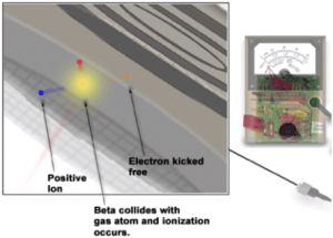
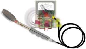
The GM Probe has a simple construction. Just under the surface, you can see a gas filled chamber connected to a simple circuit. Radiation interacts in the chamber and is changed into an electronic pulse Inside the chamber is an electrode called anode which collects the charge created by ionization from incident radiation. The electric circuit is completed by using the chamber wall as the cathode. The chamber is filled with a special gas that amplifies the signal after the ionization. Incident radiation, shown as a beta particle, passes through the thin window of the probe and into the gas filled chamber. | 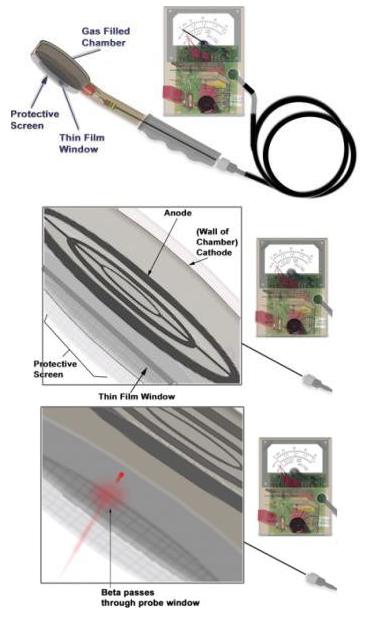 | ||
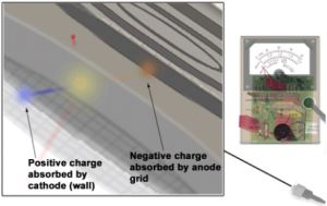
The two charges created by the ionization continue to move towards the electrodes as the beta keeps going through the chamber. The two charges then strike the electrodes and a potential forms | |||
  | |||
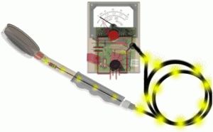
The ionization creates an electric current in the circuit. The chamber's quench gas stops the amplification from an interaction (approx. 80 microseconds) and prepares the chamber for another interaction. The electric current is processed in the scaler and sorts out the radiation interaction current pulses from the system current from the batteries.
|   | ||
| How Does the Scintillation (Nal) Probe w/ Survey Meter Work? | |||
A scintillation probe is based on the light emission by substances (i.e. a crystalline sodium-iodide salt) that emits light or "scintillates" when struck by ionizing radiation. These light flashes are collected by a photomultiplier tube, which also amplifies the signal. These sensitive components are all encased in a magnetically shielded, light tight aluminum shell. This probe is used to primarily detect low energy photons (125I) and low energy x-rays.
An incident x-ray or gamma ray passes through the probe window depositing energy in the scintillation crystal. The scintillation material converts the energy into light (scintillates). The emitted light spreads out and strikes the optical window and is transferred to the photomultiplier (PMT). At the front of the (PMT) is a window of special material called the photocathode (shown in red). When light strikes the photocathode, it produces electrons. One electron is shown ejected. The electron is pulled towards the PMT. The electron ejected from the photocathode passes into the photomultiplier. The ejected electron hits the PMT's dynodes and multiplies the number of electrons. This essentially causes an "avalanche" of electrons that result in an amplification of the original interaction.
The anode collects the electrons and forms an electronic pulse. The pulse is directed along the circuit to the scaler as a series of pulses. Inside the scaler, the signals are reported visually by a meter (needle) and audibly by clicks | 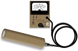 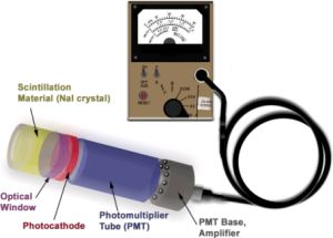 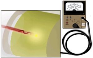 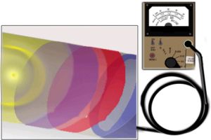 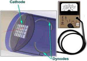 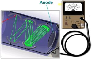 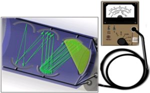 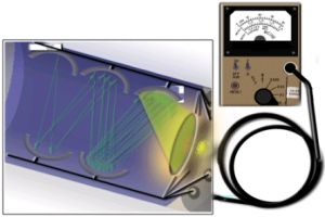 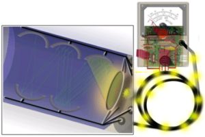 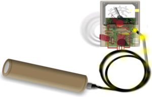 | ||
| << Previous 1 2 [3] 4 5 6 Next >> |
